How to select the buoyancy of semi-floating rubber hoses
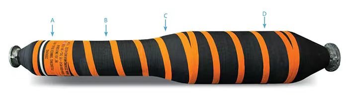
Core Concept: What is ‘Semi-Self-Floatation’? First, it is important to clarify the meaning of ‘semi-self-floatation’. It refers to a rubber pipe that, after being filled with a medium (such as water, mud, etc.), has insufficient buoyancy on its own to completely counteract gravity and float on the water surface; instead, it partially suspends in the water.
• Fully Self-Floatation: The pipe always floats on the water surface like a boat.
• Non-Self-Floatation/Negative Buoyancy: The pipe sinks to the bottom of the water.
• Semi-Self-Floatation: The pipe is partially submerged in water and partially exposed above the water surface, or needs to maintain a stable suspended height above the seabed. This design is typically used to reduce friction with the seabed, avoid obstacles, or adapt to dynamic environments.
Key Steps and Considerations for Selecting Buoyancy
Step 1: Define Operating Condition Parameters (Design Input)
This is the foundation of all calculations and must be determined first.
1. Medium Characteristics:
• Density: Density of the medium transported inside the pipe (e.g., fresh water 1000 kg/m³, seawater approximately 1025 kg/m³, mud may be higher).
• Flow velocity and pressure: Affect selection of pipe wall thickness and internal pressure.
2. Usage Environment:
• Water body: Seawater or freshwater? Seawater has a higher density and provides greater buoyancy.
• Water depth: Shallow water or deep water? Water depth affects external water pressure and overall force on the pipe.
• Sea conditions/water current: Are there wind, waves, and currents? Dynamic loads significantly impact pipe stability and may require a larger safety margin.
• Bottom conditions: Flat, rugged, or with obstacles? This determines the required suspended height above the seabed.
3. Pipe Parameters:
• Inner diameter: Determines transport capacity.
• Length: Total length.
• Rubber pipe structure and material density: Including lining layer, reinforcement layer (cotton fabric, steel wire), and outer cover layer. The materials and thickness of each layer determine the pipe’s self-weight.
Step 2: Define Buoyancy Target (Design Output)
What state do you want the pipe to present during operation?
1. Target Suspended State:
• Proportion exposed above water: For example, desire 1/3 of the pipe to be exposed above water and 2/3 submerged.
• Suspended height above seabed: For example, in static conditions, desire the bottom of the pipe to be 0.5 meters above the seabed.
• Neutral buoyancy: At a certain depth underwater, gravity and buoyancy are perfectly balanced.
For semi-self-floatation, the most common target is to maintain a specific ‘suspended height above the seabed’.
Step 3: Perform Buoyancy Calculation
The core principle is Archimedes’ Law.
Basic Formula:
• Total weight of the pipe (W_total) = Pipe self-weight (W_pipe) + Medium weight (W_media)
• Buoyancy experienced by the pipe (F_buoyancy) = Volume of water displaced by the pipe (V_displaced) × Density of water (ρ_water) × Acceleration due to gravity (g)
For semi-self-floatation, the force balance is:
Net buoyancy (F_net) = F_buoyancy – W_total
Our goal is to have F_net be a small positive value or close to zero to ensure the pipe can suspend at the target height.
Integration and Calculation of Buoyancy Materials
The buoyancy of semi-self-buoyant rubber pipes typically comes from the buoyancy materials wrapped around the outside (such as polyurethane foam, polyethylene foam, etc.). The steps to calculate the required additional buoyancy are as follows:
1. Calculate Negative Buoyancy:
– Assume the pipe is submerged in water without additional buoyancy.
– Negative Buoyancy = W_total – (Pipe Volume × ρ_water × g)
– This value is usually positive, indicating the pipe will sink.
2. Calculate Target Net Buoyancy:
– Based on the desired suspension state (e.g., height above the seabed), use a mechanical model (considering catenary principles) to back-calculate the required net buoyancy to \”lift\” the pipe to that height. This calculation can be complex and typically requires engineers to use specialized software or empirical formulas.
– Simplified Estimation: For a pipe laid flat near the seabed and intended to maintain a small height above the seabed, the target net buoyancy can be set at 5% – 20% of the negative buoyancy. For example, if the negative buoyancy is 1000N, the additional buoyancy can be designed to result in a net buoyancy of +50N to +200N.
3. Determine Volume of Buoyancy Material:
– The net buoyancy provided by the buoyancy material itself = V_foam × (ρ_water – ρ_foam) × g
– Where ρ_foam is the density of the buoyancy material. Lower density provides greater buoyancy per unit volume, but higher strength and cost.
– Required volume of buoyancy material V_foam ≈ Target Net Buoyancy / [(ρ_water – ρ_foam) × g]
4. Integration Methods of Buoyancy Materials:
– Overall Coating: Uniformly coat a layer of buoyancy material around the entire pipe.
– Segmented Floats: Install buoyancy blocks (floats) at certain intervals. This method is more common as it facilitates installation and maintenance and has a smaller impact on the pipe’s bending performance.
– If using floats, calculate the buoyancy of a single float and the total number needed.
– Number of Floats = Total Required Additional Buoyancy / Effective Buoyancy of a Single Float
Important Notes
• Safety Factor: A safety factor (typically 1.2 to 1.5) must be considered to account for uncertainties such as changes in medium density, long-term water absorption of buoyancy materials, and severe sea conditions.
• Dynamic Effects: In waves and currents, the pipeline will move, generating additional inertial forces and hydrodynamic forces, which may require greater buoyancy than static calculations.
• Performance of Buoyancy Materials: Pay attention to their water absorption rate, compressive strength (which becomes crucial with increasing water depth), and corrosion resistance.
For critical applications (such as marine engineering and dredging projects), it is strongly recommended to provide detailed parameters to rubber hose manufacturers or professional marine engineers. They can perform precise calculations and designs using their extensive experience and specialized software (such as OrcaFlex) for dynamic analysis.
In short, the essence of selecting semi-self-buoyant rubber hoses for buoyancy is: based on accurately calculating the pipeline’s own ‘downward force’, add buoyancy materials to precisely provide an ‘upward force’ that is close but slightly smaller, thereby achieving a controllable suspended state.