How to Conduct a Static Hydrostatic Test
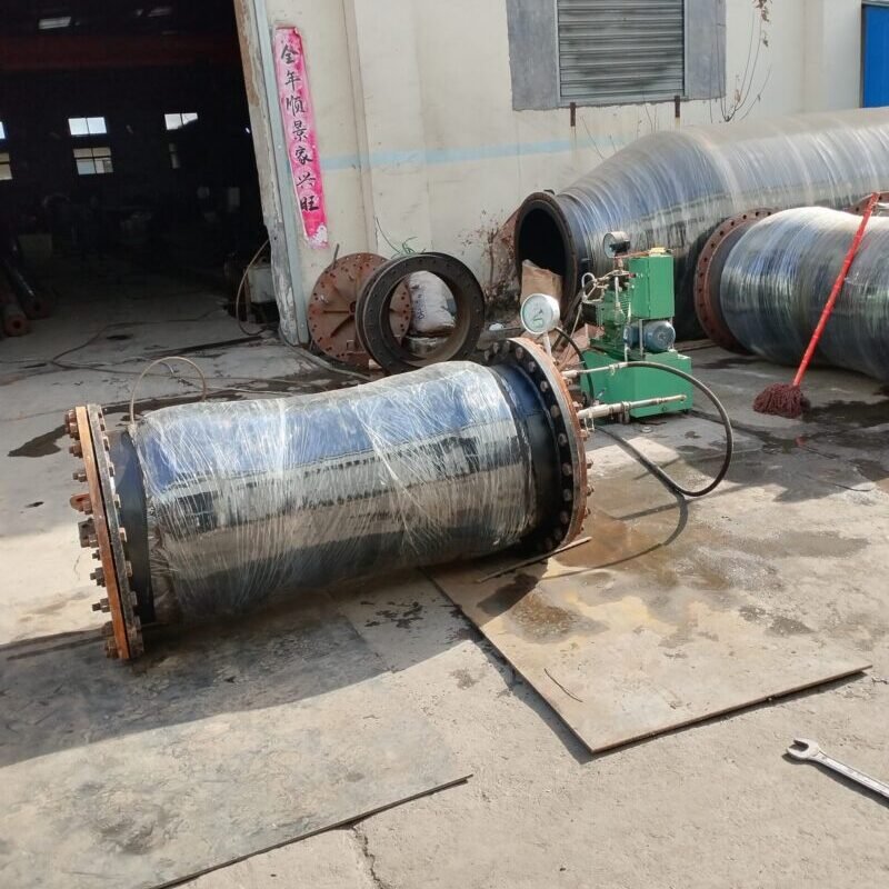
A static hydrostatic test is an important method for checking the sealing and strength of pipelines, containers, or equipment, suitable for water supply pipelines, fire protection systems, pressure vessels, etc. Here are detailed operational steps and precautions:
I. Preparations Before Testing
1. Check System Status
◦ Ensure that the tested pipeline or equipment is installed, securely fixed, and all interfaces are welded or connected.
◦ Remove debris from the system and temporarily seal all openings (such as valves, vents, branch pipes).
2. Select Test Medium
◦ Typically use clean water (avoiding corrosion), and add antifreeze in low-temperature environments.\◦ For austenitic stainless steel equipment, the chloride ion content in water should be <25 ppm (to prevent stress corrosion).
3. Install Test Equipment
◦ Connect the test pump (manual or electric) to the lowest point of the system to ensure air can be expelled during water injection.\◦ Install an air release valve at the highest point of the system to thoroughly vent air during water injection.\◦ The pressure gauge range should be 1.5 to 2 times the test pressure, with an accuracy of ≥1.6 grade, and install more than two for verification.
II. Testing Steps
1. Water Injection and Air Release
◦ Slowly inject water and observe the air release valve until continuous water flow without bubbles appears, then close the air release valve.
2. Gradual Pressure Increase
◦ Strength Test: Gradually increase pressure to 1.5 times the test pressure (e.g., if the design pressure is 1.0 MPa, then test at 1.5 MPa).
■ Increase pressure by 25% each stage, stabilize for 5 minutes to check for leaks before continuing.
◦ Tightness Test: Reduce pressure to the design pressure (e.g., 1.0 MPa) and maintain pressure for inspection.
3. Pressure Maintenance and Inspection
◦ Strength Test: After reaching the test pressure, maintain pressure ≥10 minutes (as per regulations, e.g., GB 50268).
◦ Tightness Test: Maintain pressure for over 30 minutes, with a pressure drop ≤5% being acceptable (or meeting design specifications).
◦ Inspect all welds, flanges, valves, etc., ensuring no leakage, deformation, or expansion.
4. Pressure Relief and Drainage
◦ Slowly relieve pressure to atmospheric level, open the air release valve to drain water, avoiding negative pressure damage to the system.
III. Acceptance Criteria
• No Leakage: During pressure maintenance, the pressure gauge shows no continuous decline, and all interfaces have no dripping or moisture.
• No Deformation: The pipeline/equipment has no visible expansion, cracks, or abnormal deformation.
• Pressure Drop Requirement: In tightness tests, the pressure drop ≤5% of the test pressure (e.g., if the test pressure is 1.0 MPa, the pressure drop must be ≤0.05 MPa).
IV. Safety Precautions
1. Prohibit Overpressure: Never exceed the test pressure (e.g., 1.5 times the design pressure).
2. Personnel Protection: Stay away from flanges, welds, and other potential burst points during testing.
3. Environmental Temperature: Water temperature ≥5°C, avoid low temperatures causing metal materials to become brittle.
4. Emergency Preparedness: Have a pressure relief valve and emergency drainage channel ready.
V. Common Problem Handling
• Rapid Pressure Drop: Check if air release was incomplete or there are hidden leaks (use soapy water to apply to suspicious points).
• Local Leakage: Mark the leak point, relieve pressure, repair, and retest.
According to Standards:
• Water Supply Pipelines: GB 50268 ‘Construction and Acceptance Specifications for Water Supply and Drainage Pipeline Engineering’
• Industrial Pipelines: GB/T 20801 ‘Pressure Pipeline Specifications’
• Pressure Vessels: NB/T 47013 ‘Non-destructive Testing of Pressure Equipment’
After completing the test, a written record must be formed, including pressure values, pressure maintenance time, inspection results, etc., as acceptance evidence.”