Analysis of the Differences in Suction and Discharge Operating Conditions of Dredging Rubber Expansion Joints
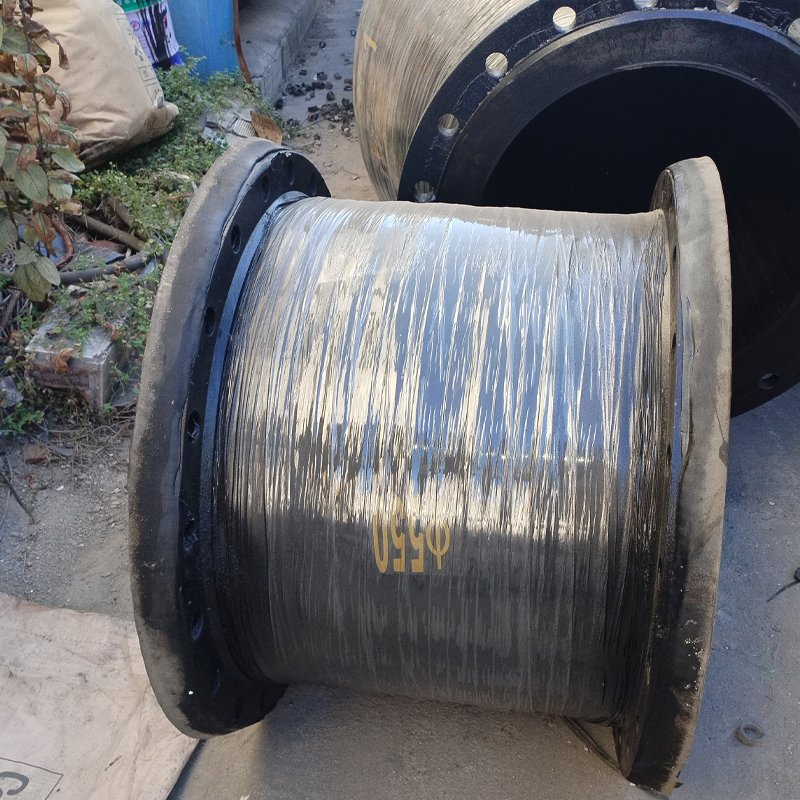
Rubber expansion joints (also known as rubber hose couplings or compensators) used in dredging projects have significant differences in their design, performance requirements, and installation usage under the two operating conditions of ‘suction’ and ‘discharge’.
Simply put, the core difference lies in the type of pressure they withstand: the suction end is subjected to negative pressure (vacuum pressure), while the discharge end is subjected to positive pressure.
Below, we will conduct a detailed comparison from multiple dimensions.
Core Difference Comparison Table
Comparison Dimension /Inlet Expansion Joint/ Outlet Expansion Joint Core Operating Condition
Negative Pressure (Vacuum)
Positive Pressure
Main Function
Compensate for pipeline alignment errors, absorb vibration and displacement at the pump inlet, and prevent air from being sucked in.
Compensate for pipeline thermal expansion and contraction and displacement, absorb the impact of high-pressure, high-flow media and severe vibration at the pump outlet.
Pressure Type
Internal pressure is lower than external atmospheric pressure.
Internal pressure is higher than external atmospheric pressure.
Failure Risk
Collapse due to atmospheric pressure. If structural strength is insufficient, the hose may be flattened by external atmospheric pressure, causing pipeline blockage.
Bursting, bulging, or tearing. If pressure resistance is inadequate, the hose will be damaged under high pressure, leading to media leakage.
Structural Design
Focus Collapse resistance rigidity.Usually adopts thicker tube walls, additional rigid rings (steel rings or steel wire rings), or internal skeleton support to prevent being sucked in. Pressure resistance strength.
Focuses on the winding structure of rubber and cord fabric (skeleton layer) and the number of layers to ensure sufficient pressure resistance capability.
Medium Flow Rate
Relatively low and unstable, may contain air.
Very high and stable, with great impact force.
Main Wear Location
Due to possible presence of unfully mixed air and silt, cavitation may be more pronounced.
Due to erosion by high-speed silt, inner wall wear is very severe, especially at bends.
Installation Location
Located before the slurry pump inlet.
Located after the slurry pump outlet.
Detailed Explanation
1. Inlet Expansion Joint
• Operating Condition: During dredging operations, the mud pump draws a mixture of mud and sand (slurry) from the riverbed or seabed through pipelines. At the pump inlet, a low-pressure zone or even a vacuum is formed, known as ‘negative pressure’.
• Core Challenge: Prevent collapse. Under negative pressure, the rubber expansion joint is subject to external atmospheric pressure that tends to flatten it. Therefore, its design priority is to ensure it does not deform or collapse under maximum vacuum.
• Structural Features:
◦ Reinforcing Rings: The most common feature is internal or external metal (typically steel) reinforcing rings. These rings are spaced along the length of the hose like bones, providing radial support to resist external pressure.
◦ Thick-Wall Design: The tube wall is usually thicker to increase rigidity.
◦ End Flanges: They need sufficient strength and sealing capability to prevent air intake under negative pressure, as any air intake would affect the pump’s efficiency (cavitation) and flow rate.
2. Outlet Expansion Joint
• Operating Condition: The mud pump pressurizes the drawn slurry and transports it through pipelines to discharge points hundreds of meters or even several kilometers away. The pressure here is very high, ranging from several kilograms to tens of kilograms per square centimeter.
• Core Challenge: Withstand high pressure and wear. The expansion joint must be able to withstand the system’s highest internal pressure without bursting or excessive expansion. Meanwhile, the high-speed flowing mud and sand mixture cause intense scouring and wear on the pipeline inner wall.
• Structural Features:
◦ High-Strength Skeletal Layer: The pressure-bearing capacity mainly comes from multiple layers of high-strength fabric (such as nylon, polyester, or aramid) skeletal layers. These fabrics are wound at specific angles to provide strong pressure resistance.
◦ Wear-Resistant Liner: The inner rubber layer typically uses an extremely wear-resistant formula (such as high-content polyurethane or special synthetic rubber) to extend service life under high-speed mud and sand scouring.
◦ Impact-Resistant Design: It needs to withstand water hammer impacts caused by pump start/stop, valve opening/closing operations.
Summary and Selection Key Point
When selecting rubber expansion joints for dredging, it is essential to strictly distinguish between inlet and outlet operating conditions:
• Never Mix-Use: Using an outlet-designed expansion joint on the inlet may cause it to be sucked flat instantly during startup. Conversely, using an inlet expansion joint on the outlet may lead to bursting due to inability to withstand high pressure.
• Key Parameters:
◦ For Inlet: Maximum vacuum (e.g., -0.1 MPa) and anti-collapse capability are primary considerations.
◦ For Outlet: Maximum working pressure (e.g., 2.0 MPa), burst pressure, and wear resistance are primary considerations.
• Common Requirements: Regardless of inlet or outlet, they need good displacement compensation capability (axial, lateral, angular), corrosion resistance (seawater, mud and sand), and fatigue resistance.
Therefore, when purchasing or replacing rubber expansion joints on dredging pipelines, it is imperative to clearly specify the exact application location (inlet before the pump or outlet after the pump) and the corresponding vacuum or pressure rating to the supplier, ensuring the correct product is selected to guarantee operational safety and efficiency.